Calle Larga PV Plant — Tracker Control System (TCU / NCU / Control Box)
Consolidated documentation of the installed tracker control hardware and compatibility assessment
against the proposed Solarsurges replacement. Prepared for vendor evaluation: input power & cabling,
connectors, and PV-module compatibility.
Plant · PMGD Calle Larga SpA, Calle Larga, Valparaíso Region, ChilePrepared by · iEnergiaDate · July 2026Status · For vendor review — items marked TO BE CONFIRMED require vendor input
81
Trackers
86
Motors / TCUs
1
NCU (plant-wide)
353
Strings × 29 modules
~10,237
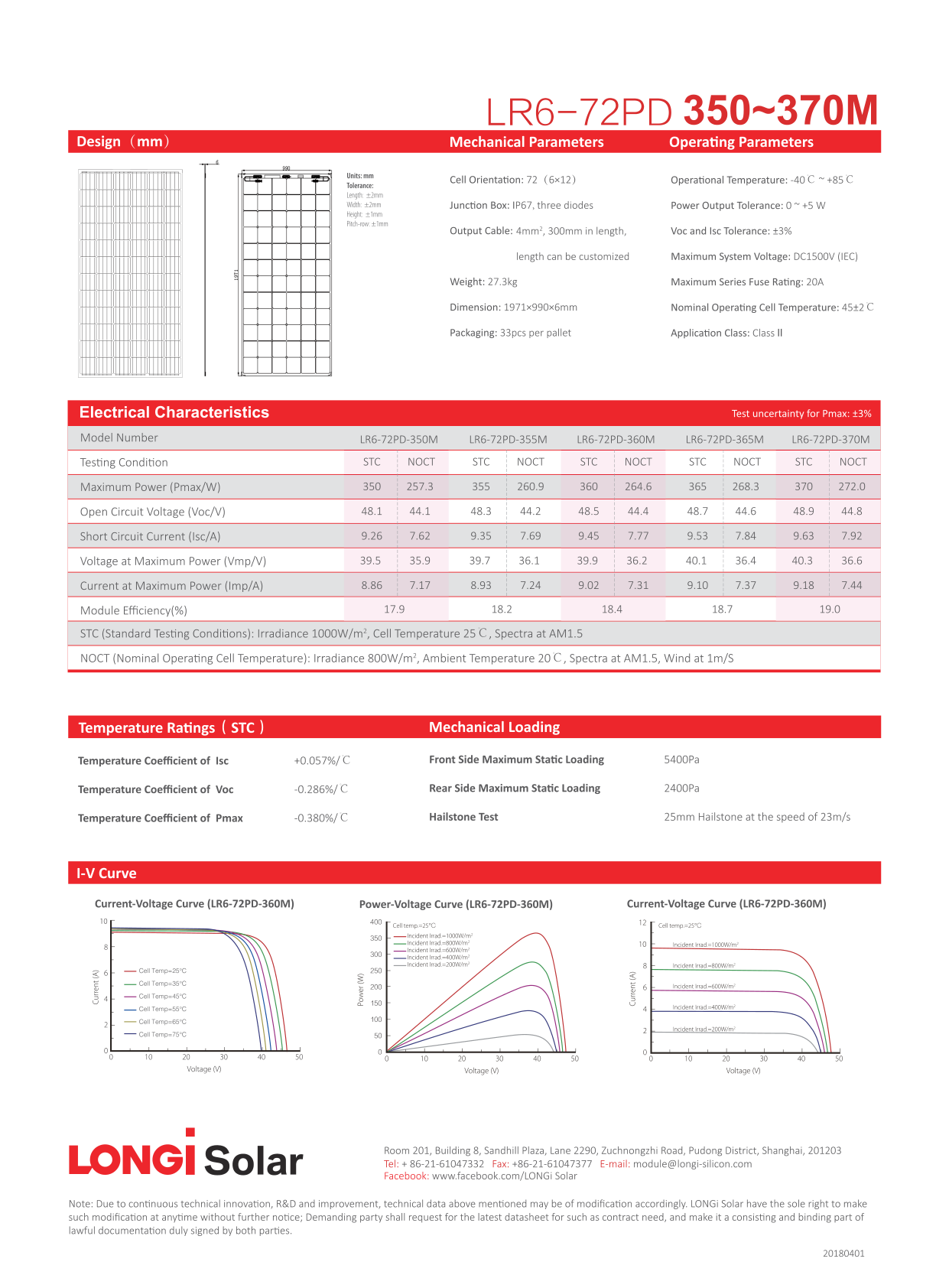
Longi LR6-72PD modules
2.4 GHz
Zigbee field network
1Executive Summary
Calle Larga operates Alion Energy Storm Tracker (AST) single-axis trackers controlled by
P4Q Electronics "Suntrack" electronics: 86 self-powered Tracker Control Units (TCU) — one per motor —
coordinated by a single Network Control Unit (NCU) over a wireless Zigbee 2.4 GHz Modbus mesh.
Each TCU is powered by its own dedicated 30 W auxiliary PV panel and LiFePO4 battery, so
no power or communication cabling runs to the trackers.
The prospective vendor (Shanghai Solarsurges Technology Co., Ltd.) has stated that both the TCU and the
NCU should be replaced. This brief confirms that position is technically forced: the Solarsurges field radio
(Sub-1GHz / LoRa mesh) is not interoperable with the installed Zigbee network, so a partial or mixed
fleet is not possible — the retrofit must swap the NCU and all 86 TCUs (plus the wind sensor unit) in one campaign.
Key compatibility picture: the self-powered architecture matches (no new field cabling); NCU supply
voltage matches (220–230 VAC); PV modules are unaffected by a controller-only swap. The three items that decide
feasibility are: (1) the replacement TCU's motor drive rating against the Alion 24 VDC slew-drive motors,
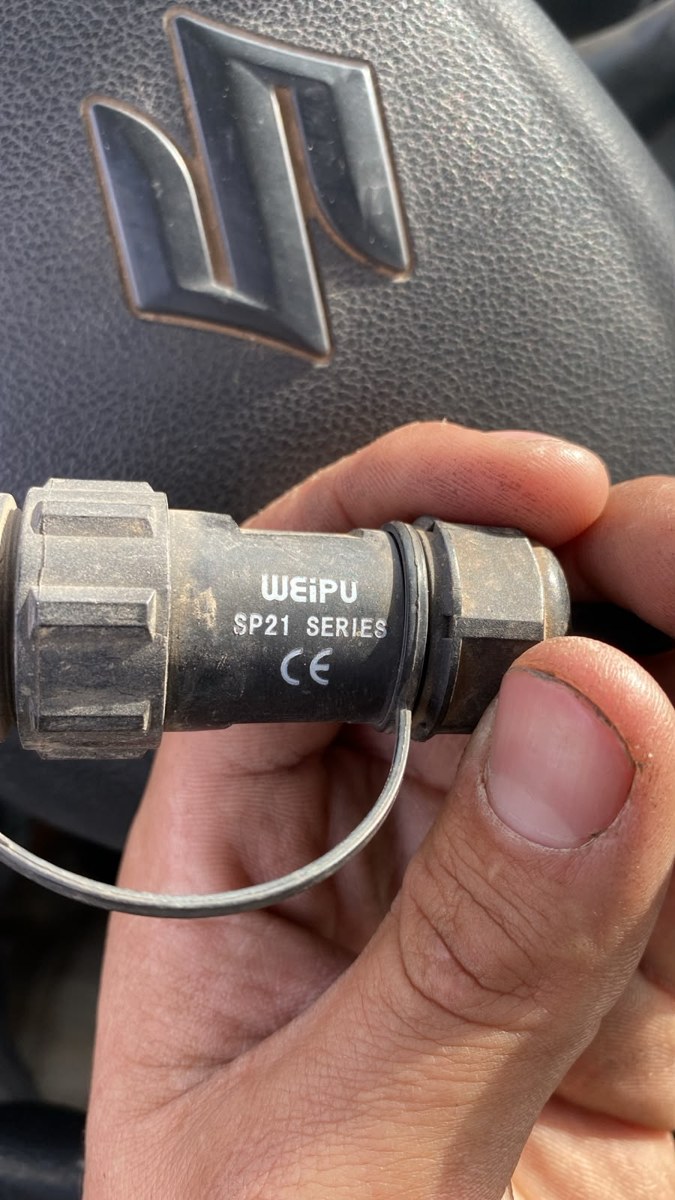
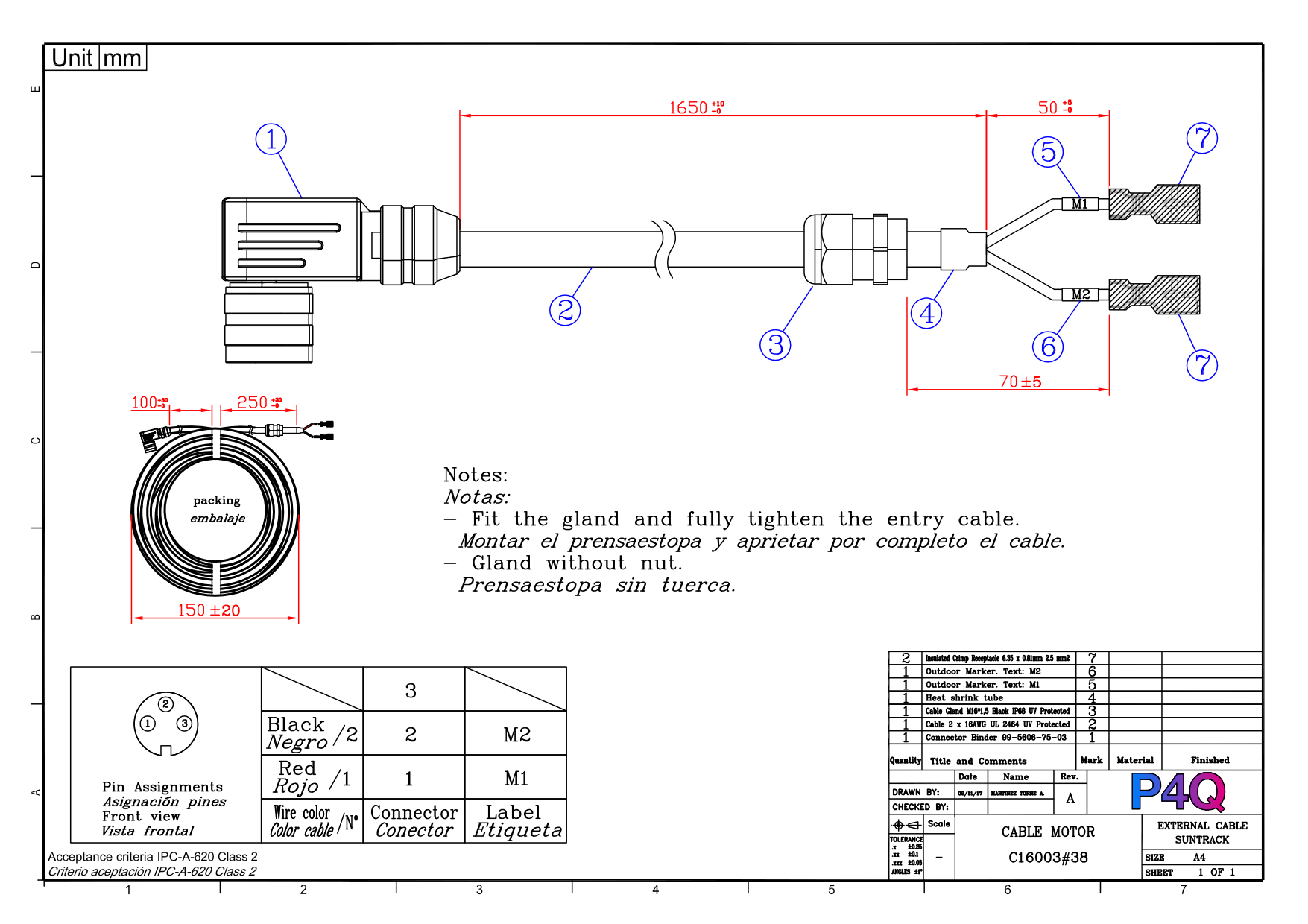
(2) mating or re-terminating the motor connector present on all 86 motor pigtails (field-verified as WEIPU SP21 series 3-pin screw-coupling; P4Q drawings state Binder 99-5606-75-03), and
(3) SCADA re-integration and Chilean RF homologation. Section 5 lists every point the vendor must confirm.
2Installed System
All values below are extracted from the original manufacturer documentation and as-built drawings held
by iEnergia. Each claim carries its source document and page.
Panel: WEIPU SP1312/S4C · aerial plug: WEIPU SP1310/P4 Type I. Pin 1 3V3 · Pin 2 RS485 power · Pin 3 RS485 − · Pin 4 RS485 +
service use only (USB-RS485 converter)
IM p.25
ZB (radio)
Zigbee antenna, 300 mm flying lead, hangs loose downward
—
IM p.24
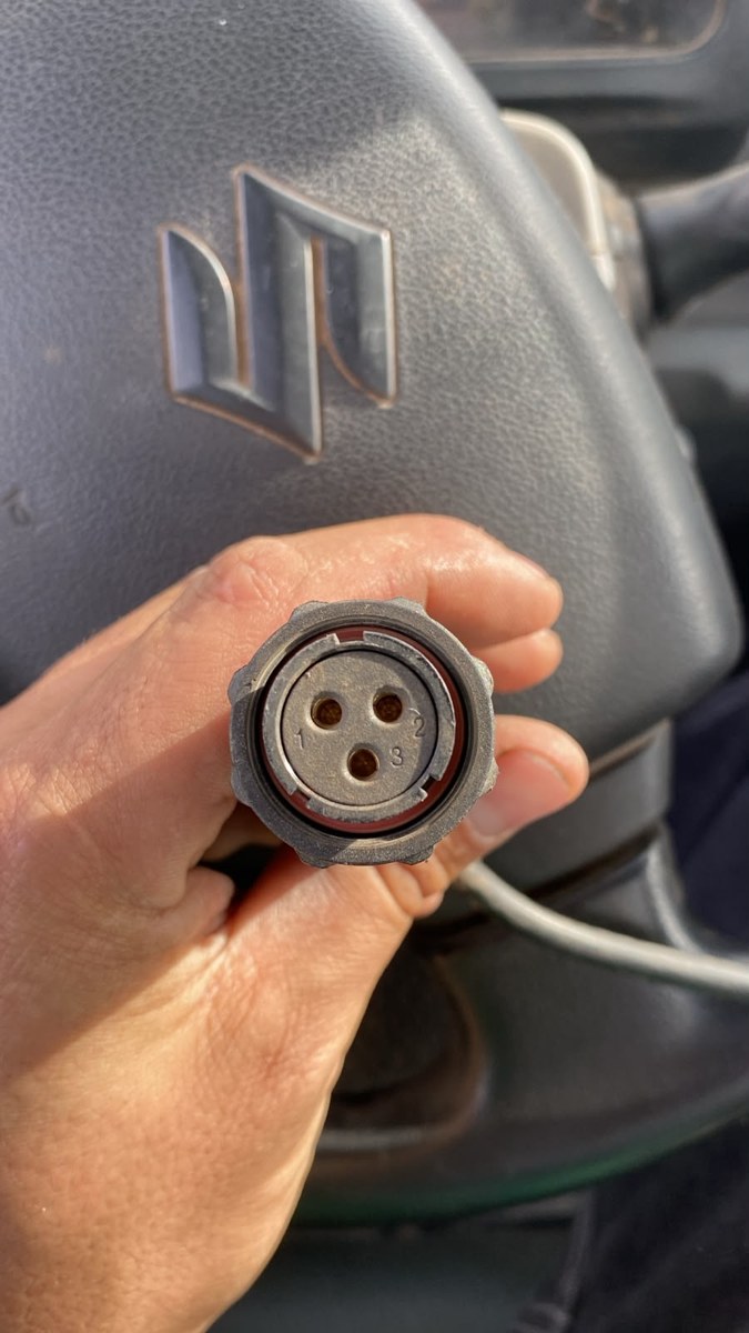
Motor connector — field verification (13-Jul-2026), side view. Body marked WEIPU SP21 SERIES, CE; screw-thread coupling ring. This is the connector actually installed on the TCU→motor circuit — it differs from the Binder part in the P4Q drawings. — iEnergia site photoMotor connector — mating face. 3 female contacts numbered 1 / 2 / 3 (consistent with documented pinout: 1 = Motor −, 2 = Motor +, 3 = NC). — iEnergia site photo, 13-Jul-2026
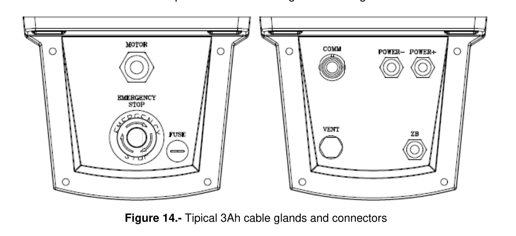
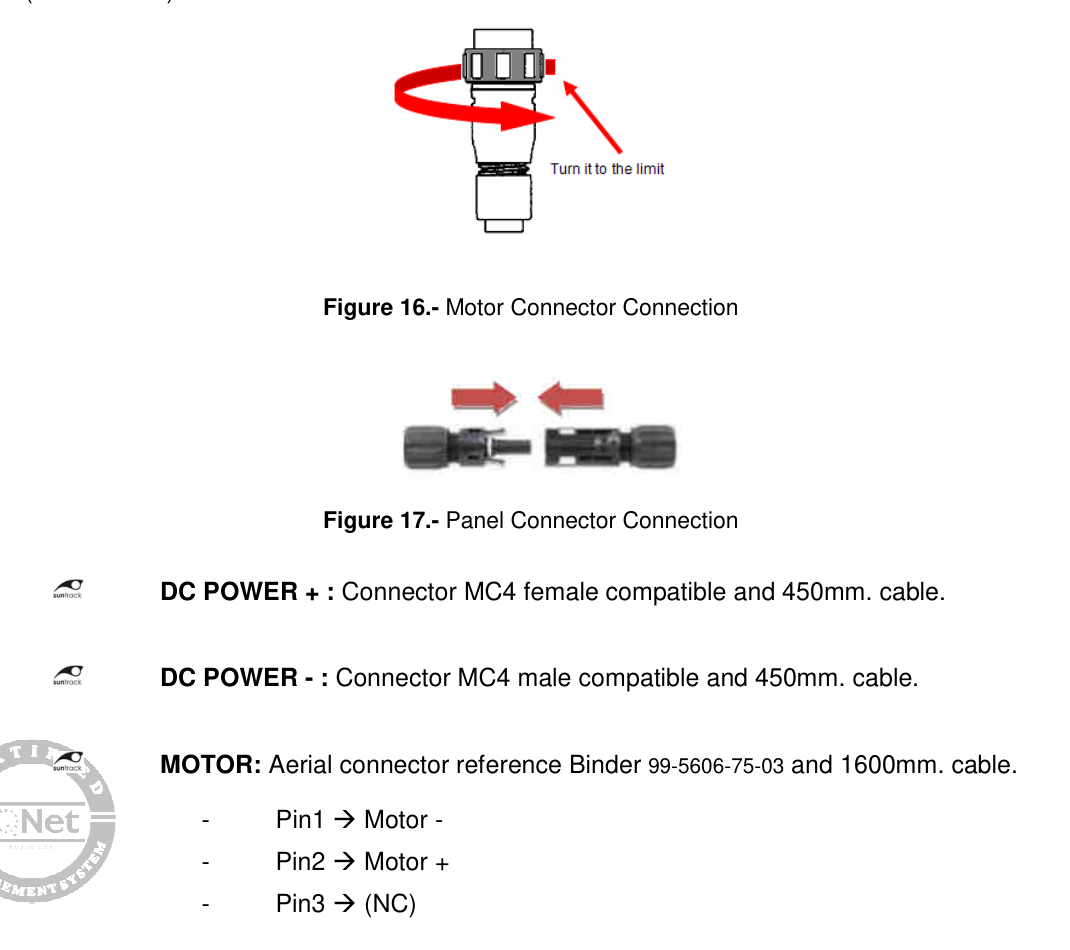
TCU connector faces (3Ah variant). Left face: MOTOR, EMERGENCY STOP, FUSE. Right face: COMM, POWER−, POWER+, VENT, ZB antenna. — P4Q Installation & Maintenance Manual D002-PS17026, p.23, Fig. 14Motor & panel connector reference. Bayonet-locking motor connector (Binder 99-5606-75-03) and MC4-compatible power pair. — Installation Manual D002-PS17026, p.24, Figs. 16–17
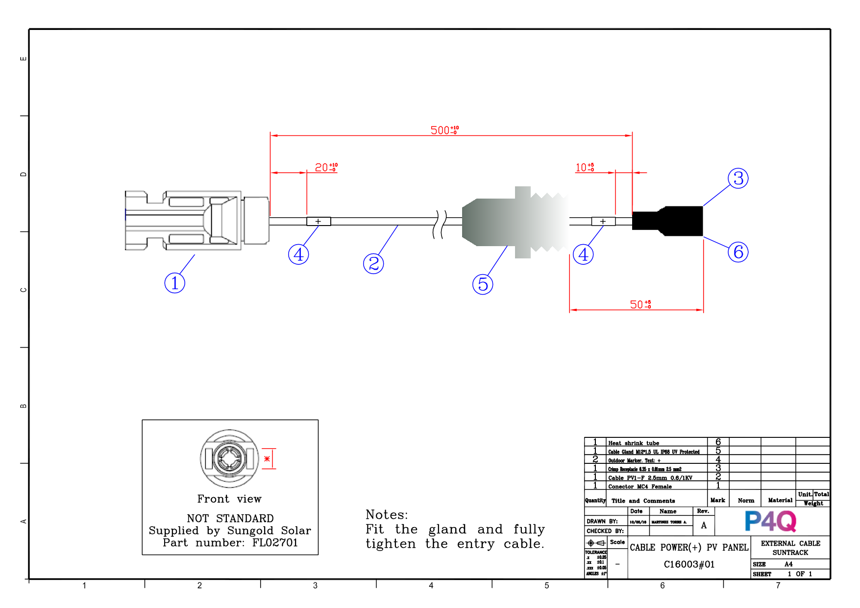
Motor cable assembly drawing. Binder 99-5606-75-03 connector, 2×16 AWG UL2464 cable, 1650 mm, pin/color table (Red/1→M1, Black/2→M2). — P4Q drawing ASSY-C16003#38 Rev A, sheet 1Aux-panel power (+) cable drawing. MC4-compatible female (non-standard, Sungold Solar FL02701), PV1-F 2.5 mm² 0.6/1 kV. — P4Q drawing ASSY-C16003#01 Rev A, sheet 1
Internal, Kionix KX-023 3-axis, 0.2° accuracy @25 °C — no external position sensor on the tracker DS p.12
Tracking precision
0.1°; backtracking supported IM p.12
Firmware updates
Local, from SCADA/NCU, or from PC over the field network (remote-update tooling used on site) DS p.13
2.3 Field communications
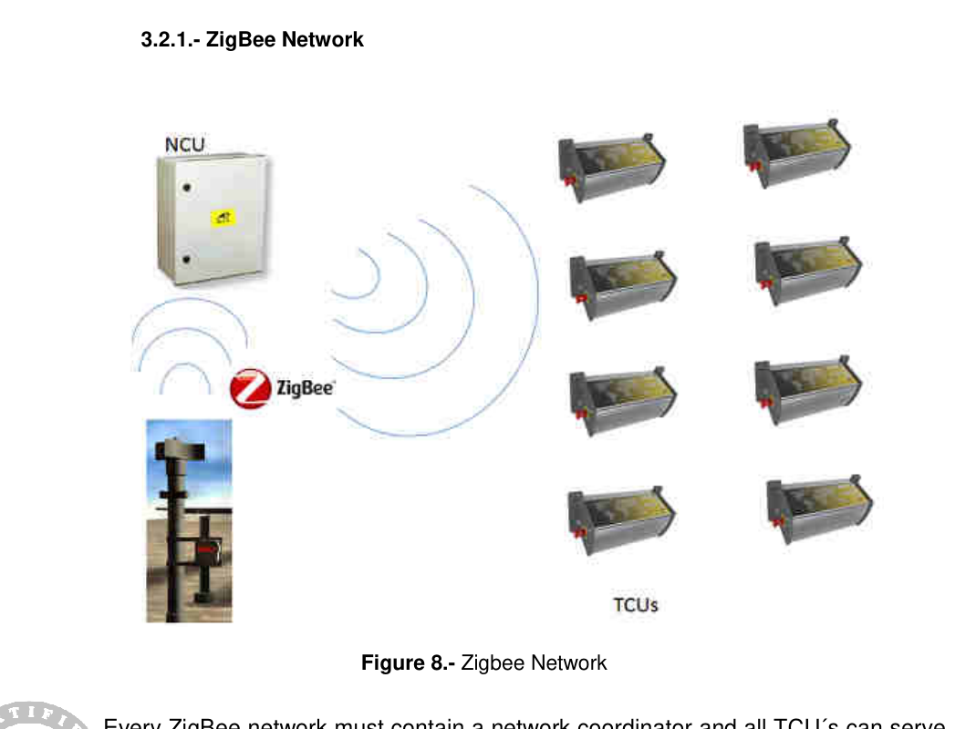
Installed field network: Modbus over Zigbee 2.4 GHz (ETSI EN 300 328), 128-bit AES, 250 kbps, ~1200 m line-of-sight,
mesh topology — every TCU can act as a router; the NCU is the network coordinator.
DS p.11 · IM p.17
Any replacement using a different radio (e.g. Sub-1GHz / LoRa) cannot coexist with the installed fleet — mixed operation is not possible.
Installed Zigbee mesh topology. NCU as coordinator, TCUs as routers. — Installation Manual D002-PS17026, p.17, Fig. 8
2.4 NCU — P4Q Suntrack Network Control Unit X12092#09 (×1, plant-wide)
Function
Gateway tracker network ↔ SCADA; centralizes positions/alarms; wind-alarm logic sends fleet to safe position; cleaning-position groups 1–8 via disconnect terminal block NCU p.3,10,24
Enclosure ("control box")
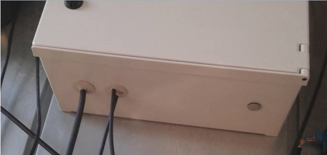
Safybox BRES-54 hot-pressed polyester, 500 × 400 × 200 mm, IP66 / IK10, RAL-7035, −30…+120 °C, door opens >180°; ~10.5 kg installed; wall/frame mounted outdoors, connectors at bottom via double-membrane seals + antenna bulkhead BRES cat. · NCU p.11,23
Power input
100–240 VAC nominal (90–264 VAC range), 50–60 Hz; < 0.80 A @115 V / < 0.60 A @230 V; plant feeds 230 VAC NCU p.10 · PLA-COM-01
Internal PSU
Delta DRC-24V30W1AZ: 24 VDC / 1.25 A / 30 W, DIN rail, Class II double-isolated Delta DS p.1–2
Protections
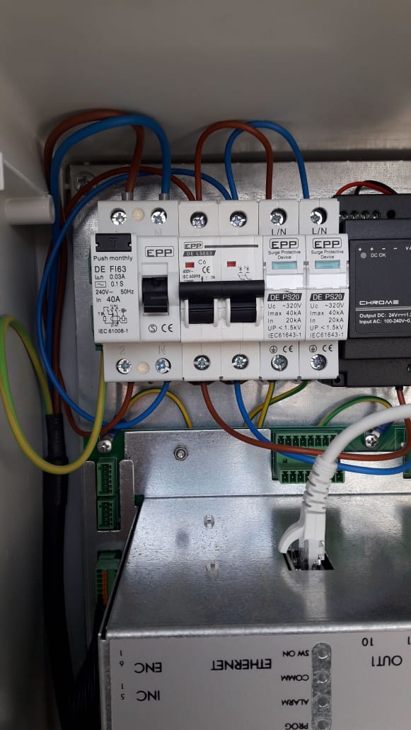
RCCB EPP DE F63 40 A / 30 mA + MCB C6 + 2× surge arresters EPP DE PS20 (Uc < 320 V, Imax 40 kA, IEC 61643-1); internal 320 V varistor Site photo · NCU p.10
CPU
CPU-Control Suntrack 32H; status LEDs (SW On / Comm / Alarm / Prog); internal RTC backup battery NCU p.25–27
Ethernet — Modbus TCP to the plant monitoring system (GreenPowerMonitor) via fiber/switch in the inverter station; internal 5-port Ethernet switch (Sixnet SLX-5ES-1); fixed IP on plant LAN; published register map covering the 86 motor addresses PLA-COM-01 · map revD
Environment
−25…+65 °C operating NCU p.10
Standards
EMC 2004/108/CE — EN 61000-6-2/-6-4, EN 55011, EN 61000-4-x series; CE NCU p.29
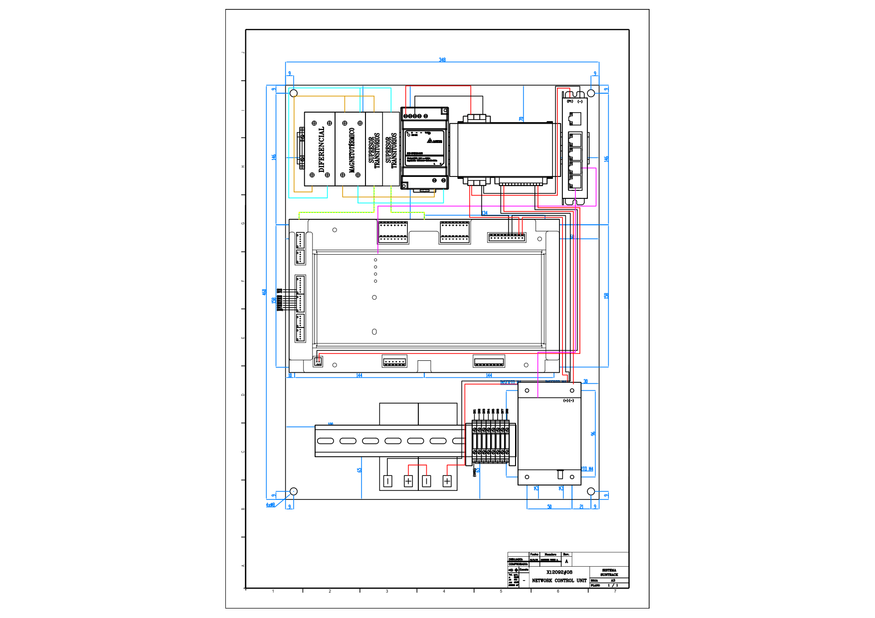
Installed NCU cabinet at Calle Larga (field photo, Apr 2019). Top row: RCCB EPP DE F63 (40 A, 30 mA), MCB C6, 2× EPP DE PS20 surge arresters, Delta Chrome 24 V PSU. Below: CPU-Control Suntrack 32H with Ethernet port. — iEnergia O&M photo archiveNCU internal assembly drawing. Backplate layout: RCCB / MCB / surge arresters / PSU, Suntrack 32H CPU board, 5-port Ethernet switch, DIN terminal blocks, gateway. — P4Q drawing ASSY-X12092 Rev A, sheet 1
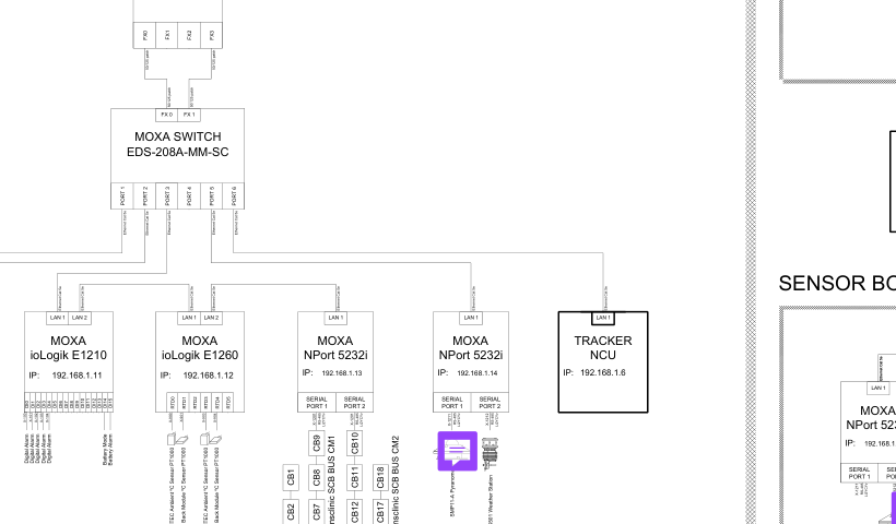
NCU cable entries. Bottom-face membrane seals for power and communications cables. — P4Q NCU technical data (NCU_Cable Access)NCU integration into plant monitoring (as-built). The tracker NCU connects over Ethernet to the plant switch and is polled by the GreenPowerMonitor SCADA. — As-built drawing PLA-COM-01 "Diagrama en Bloques", sheet 1 (detail)
2.5 Wind / weather sensing — Suntrack RSU
Unit
Suntrack RSU (Remote Sensor Unit), ASA enclosure 348 × 276 × 190 mm, IP67, −25…+70 °C RSU DS p.1–6
Power
90–264 VAC single-phase, 12.5 W typical (internal Delta 24 V/10 W PSU) RSU DS p.7
Sensors
Anemometer ANEMO4403 (+ snow sensor type 260-700 documented); up to 5 sensor inputs (RS-485 / analog / digital) RSU DS p.1,4
Controller-only swap — modules, clamps and purlins are untouched. Module data provided for electrical context (string-powered options, aux panel siting).
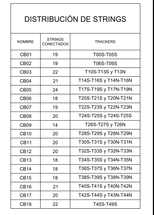
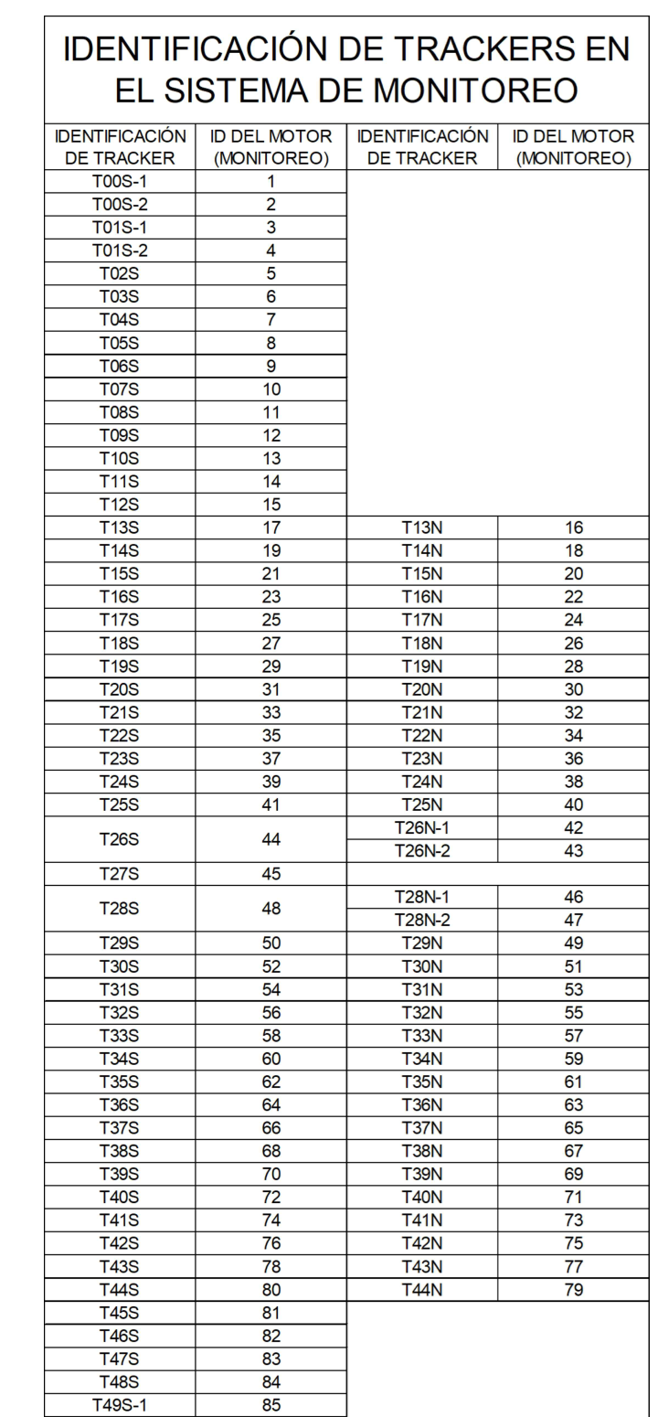
String distribution (as-built). CB01–CB18 with connected strings and tracker ranges. — PLA-T-01 As Built, detailTracker → motor ID map (monitoring system). 86 motor IDs; dual-motor trackers appear as -1/-2. — PLA-T-01 As Built, detail
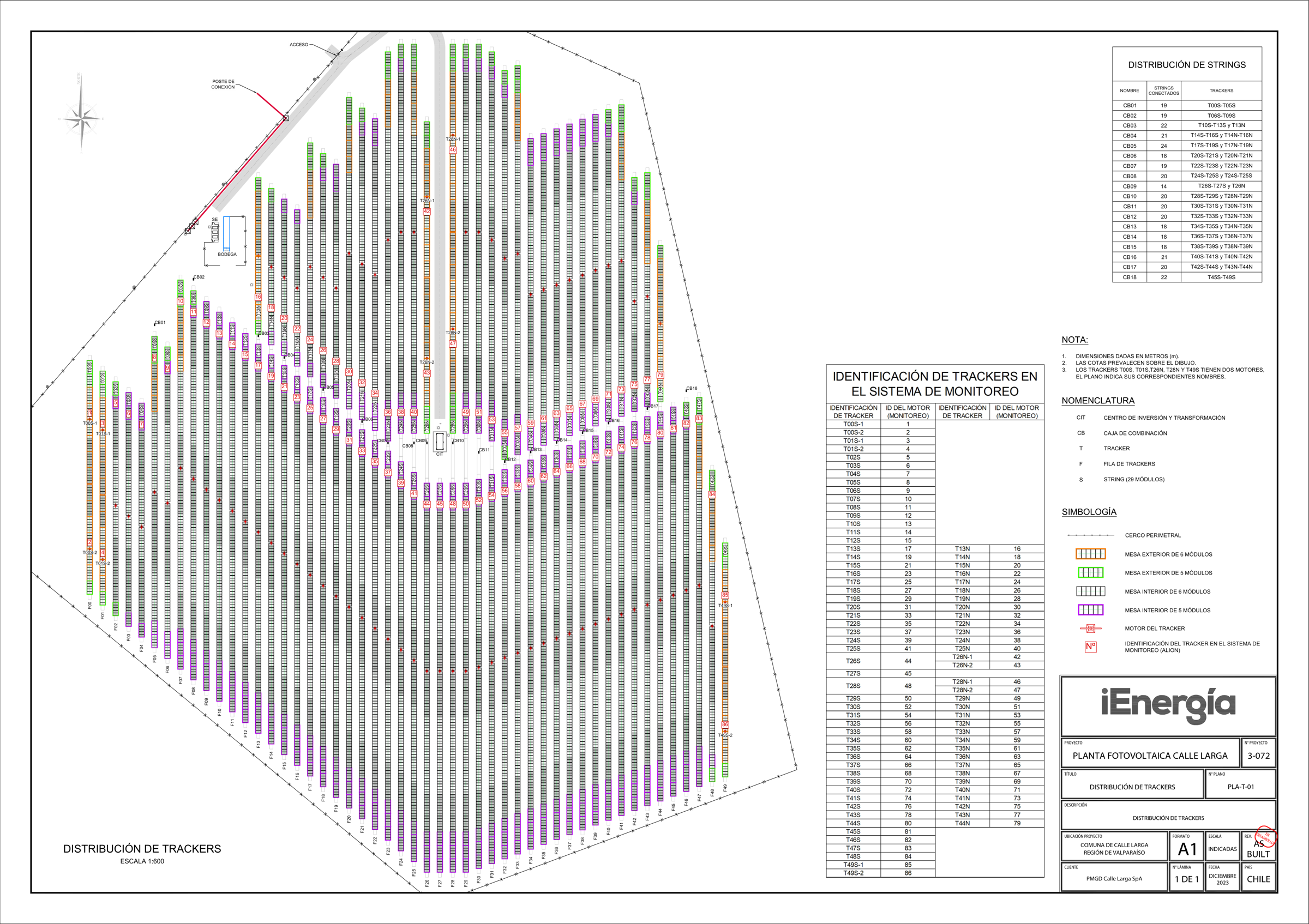
Tracker distribution — full as-built layout. South field (T00S–T49S) and north field (T13N–T44N); motor positions marked; combiner boxes CB01–CB18; inverter station (CIT) at center. — PLA-T-01 "Distribución de Trackers", As Built rev. Dec 2023
3Proposed System — Solarsurges
Extracted from the Solarsurges Company Profile & Product Brochure (EN, 12 pages, doc. dated 2026-07-06).
The brochure is a company-profile document: it does not state connector types, cable specifications, pinouts,
dimensions, weights or mounting details — those gaps are flagged and consolidated in Section 5.
TCU — Surge Track S350 (closest match to installed architecture)
Power supply
Self-Powered or String-Powered (current-source technology, "no pony panel needed") Bro p.3
Aux PV panel (self-powered)
60 W / "customizable" — voltage window TO BE CONFIRMEDBro p.3
Battery
LiFePO4, 25.6 V, 3.4 Ah / 6 Ah, CC-CV Bro p.3
Motor type
Brushless / Brushed — voltage & current rating TO BE CONFIRMEDBro p.3
IEC 62817 · Chile RF homologation (SUBTEL) · UN38.3 · warranty terms — TO BE CONFIRMED
4Compatibility Matrix
Verdict per row: ✅ compatible⚠️ needs adapter / verification❌ mismatchTO BE CONFIRMED.
Scope: controllers only — Alion tracker mechanics and Longi modules remain in place.
4.1 Input power & cabling
Item
Installed (P4Q Suntrack)
Proposed (Solarsurges)
Verdict
TCU supply architecture
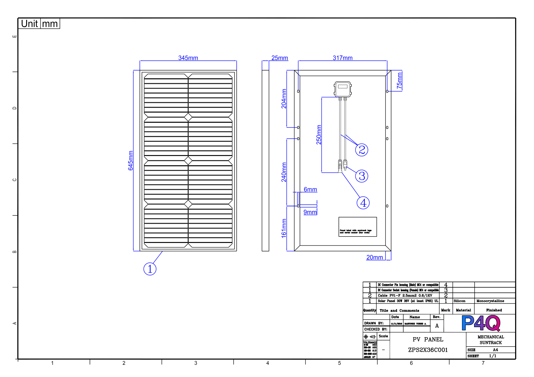
Self-powered: 30 W/36 V aux panel + LiFePO4 25.6 V — zero field cabling
S350 self-powered (60 W / customizable panel) or string-powered; LiFePO4 25.6 V
Alion AST rotation > ±60°; TCU tracks with internal inclinometer
−60…+60° range; astronomical + position sensor
✅ range matches
Stow interlock
Storm-Lock (Geneva mechanism) engages at stow
Stow logic parameters not stated
TO CONFIRM
TCU mounting
Bracket on A-frame; 4 holes, 317×129 mm pattern, shared with aux panel
Dimensions / mounting not stated
TO CONFIRM
Dual-motor trackers
5 trackers (T00S, T01S, T26N, T28N, T49S) run 2 motors = 2 TCUs each today
1C2C mode: one controller, two synchronized drives (±0.3°)
✅ opportunity — verify fit
Environmental rating
TCU IP65, −10…+60 °C / NCU IP66 IK10
TCU IP67, −35…+60 °C / NCU IP65
✅ TCU better⚠️ NCU box
4.5 Certifications
Item
Installed
Proposed
Verdict
CE / EMC
CE; IEC 61000 series (test reports on file)
CE, EMC claimed
✅ nominal — request reports
Tracker-controller qualification
IEC 62817 test reports on file
Not stated
TO CONFIRM
Radio certification
ETSI EN 300 328 (2.4 GHz)
Not stated; Chile homologation unknown
TO CONFIRM
Battery transport
UL1642 cells; IATA lithium procedures documented
LiFePO4 stated; UN38.3 not stated
TO CONFIRM
Bottom line. (1) Self-powered architecture matches — no new LV cabling, provided aux-panel reuse and motor-current
margins are confirmed. (2) The single hard physical interface is the motor connector on 86 pigtails — field-verified as WEIPU SP21 series screw-coupling (documentation states Binder 99-5606-75-03).
(3) Modules are untouched. (4) The decisive mismatch is the radio: Zigbee vs Sub-1GHz forces a one-campaign full-fleet swap
plus SCADA re-integration and Chilean RF homologation.
5Open Questions — Vendor Checklist
Every item marked TO BE CONFIRMED above maps to this checklist.
V = answer expected from Solarsurges · iE = iEnergia internal verification.
A · Motor drive & power (critical)
A1Maximum continuous and peak motor current of the S350 TCU (and MD0X drive) at 24 VDC. Installed motors run ≤ 6 A with a > 15.5 A overcurrent flag.V
A2Can the S350 charge from the existing 30 W / 36 V aux panels (input window 26–40 VDC today), or does it require its stated 60 W panel?V
A3If new aux panels are required: dimensions, weight, connector type, and bracket interface for 86 positions.V
A4Confirm installed battery size (3 Ah vs 6 Ah packs) by field check / purchase records.iE
A5Motor duty cycle supported (pulse / rest profile) vs the installed limit of 30 s @ max current + 10 s rest.V
B · Connectors & cabling (critical)
B1Motor connector: does the new TCU mate the WEIPU SP21 series 3-pin screw-coupling connector (field-verified; P4Q documentation states Binder 99-5606-75-03 — sample a few more trackers to confirm fleet uniformity) directly, via adapter cable, or does it require re-terminating 86 motor pigtails?V
B3Aux-panel connector type (standard MC4?). Note the existing female is a non-standard MC4-compatible part.V
B4Physical wired service port (RS-485) available besides Bluetooth? Connector type?V
B5NCU enclosure: model, IP/IK rating, dimensions, cable entries, antenna bulkhead. Is an outdoor cabinet (≥ IP66, like today's) included?V
C · Communications & SCADA (critical)
C1Exact Sub-1GHz operating band and channel plan; SUBTEL (Chile) homologation status for TCU, NCU and any 4G module.V
C2Does the NCU expose a Modbus TCP server over Ethernet (not only Modbus RTU / MQTT)? Provide the full register map.V
C3Who performs the plant-SCADA (GreenPowerMonitor) re-integration, and is SurgeTrack SCADA mandatory or optional?V / iE
C4RF coverage design for 81 trackers on this layout: is one NCU still sufficient (as today), or are repeaters / multiple NCUs proposed?V
C5Weather station: sensor list, accuracy, mounting and power; can the existing anemometer be reused?V
C6Is the wind-stow threshold configurable? (brochure fixes 18 m/s; site threshold must match the Alion structural specification.)V
D · Mechanical & site integration
D1TCU dimensions, weight and mounting pattern; adapter plates for the existing 317 × 129 mm bracket or new brackets for 86 positions?V
D2Inclinometer: internal or external? Accuracy? Mounting-orientation constraints on the Alion A-frame.V
D31C2C applicability to the 5 dual-motor trackers: these are two independent drives on one long single-axis tracker — not a dual-axis system.V
D4Stow behavior compatibility with the Alion Storm-Lock mechanism: stow angle and approach profile.V
D5Backtracking commissioning: who loads row-geometry parameters and validates tracking after the swap?V / iE
E · Certifications, quality & commercial
E1IEC 62817 design-qualification report for the proposed TCU (exists for the installed unit).V
E2EMC / CE test reports (not only marks) and surge-immunity class.V
E3UN38.3 + IATA documentation for LiFePO4 packs shipped to Chile.V
E4Warranty term and RMA process (brochure states none).V
E5OTA firmware security model (signing, rollback) for TCU and NCU.V
E6Contactable references for retrofit projects on third-party trackers (brochure lists one "tracking system upgrade" project).V
E7Spare-parts availability commitment (years) for the proposed hardware generation.V
6Annex — Drawings & Photos
Every figure references its source document and page. Additional documentation (full manuals, datasheets,
Modbus maps, IEC 62817 reports) can be shared on request under NDA.
TCU connector faces. P4Q Installation Manual D002-PS17026, p.23Motor / panel connector reference. Installation Manual, p.24Motor connector as installed — WEIPU SP21 series. Site photo, 13-Jul-2026Motor connector mating face (3 contacts). Site photo, 13-Jul-2026Motor cable drawing (documents Binder 99-5606-75-03 — installed part is WEIPU SP21). ASSY-C16003#38 Rev APower (+) cable drawing (MC4). ASSY-C16003#01 Rev A30 W / 36 V aux PV panel. P4Q drawing ZPS2X36C001Zigbee mesh topology. Installation Manual, p.17NCU internal assembly. ASSY-X12092 Rev AInstalled NCU cabinet (site photo, 2019). iEnergia O&M archiveNCU cable entries. P4Q NCU technical dataNCU ↔ SCADA integration (as-built detail). PLA-COM-01String distribution CB01–CB18. PLA-T-01 As BuiltTracker → motor ID map (86 IDs). PLA-T-01 As BuiltLongi LR6-72PD 350–370M datasheet. Longi Solar, 2018-04-01Tracker distribution layout. PLA-T-01 As Built, Dec 2023
Original documents — cabling & connections (download)
Original manufacturer PDFs covering the cable assemblies and connection interfaces of the installed TCU,
provided for direct engineering verification of connector and cable compatibility.
Document
Content
Size
Download
ASSY-C16003#38 Rev A — Motor cable
Motor cable assembly: Binder 99-5606-75-03 connector, pin/color table, 2×16 AWG UL2464 cable, gland M16×1.5, crimp receptacles. Note: installed connector field-verified as WEIPU SP21 series (see §2.1 photos)